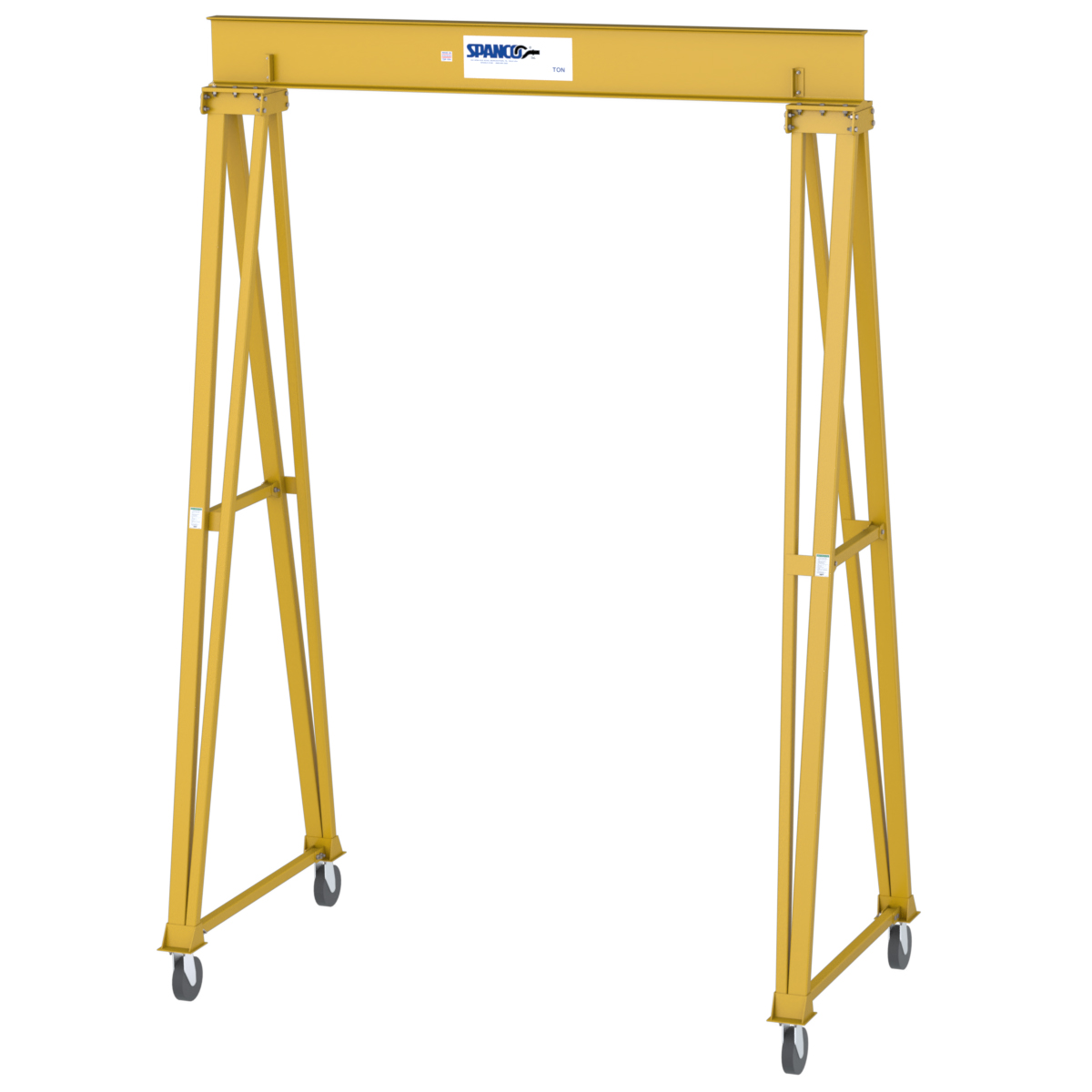
T-Series Gantry Cranes
T-Series Gantry Cranes are available in two models:
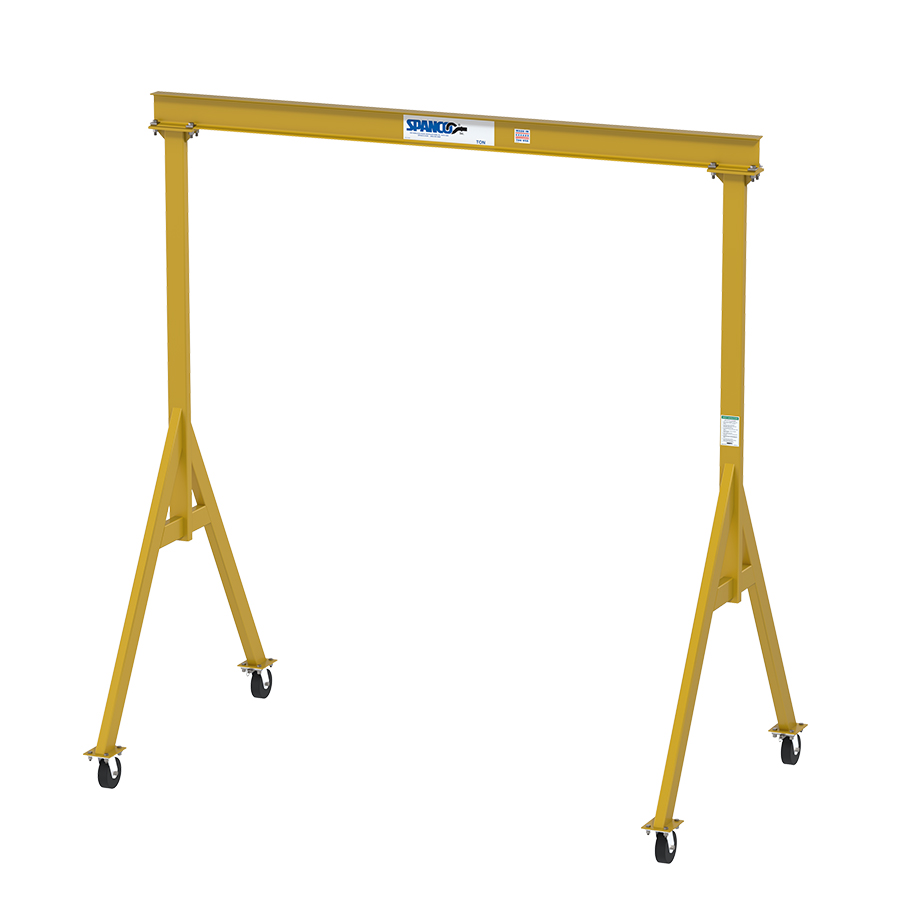
- All Steel
- Capacities: up to 10 tons
- Adjustable Overall Height: up to 24’ 3″
- Adjustable Spans: up to 40′
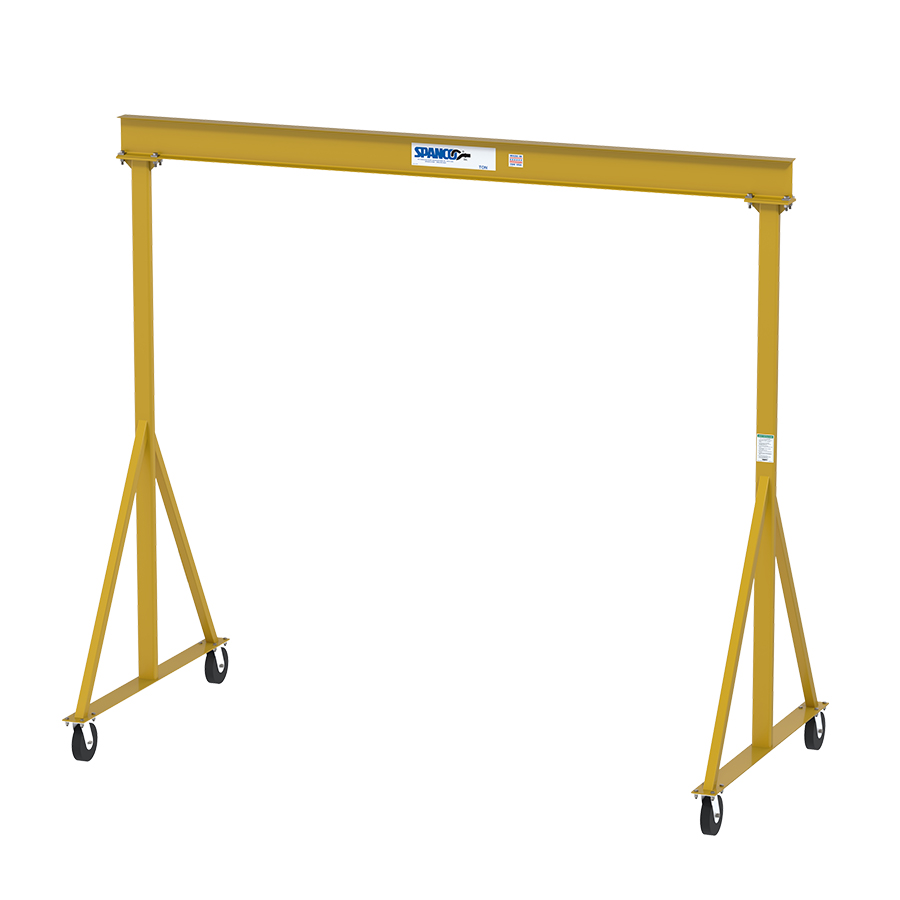
- Aluminum I-Beam
- Capacities: up to 3 tons
- Adjustable Overall Height: up to 22′
- Adjustable Span Length: up to 15′
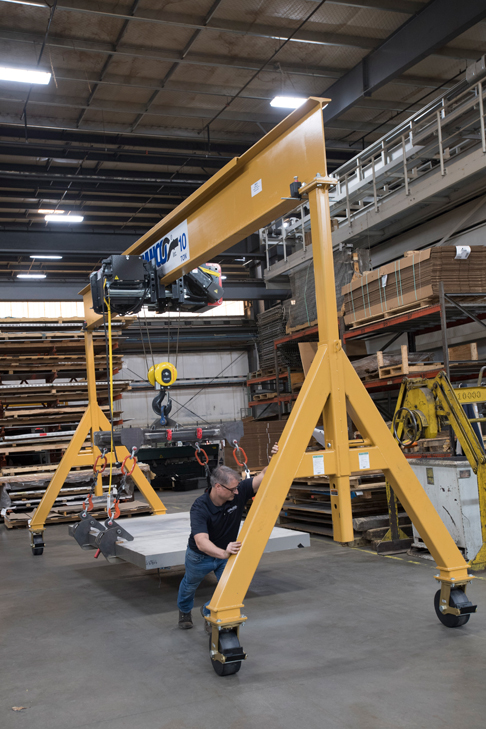
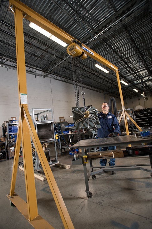
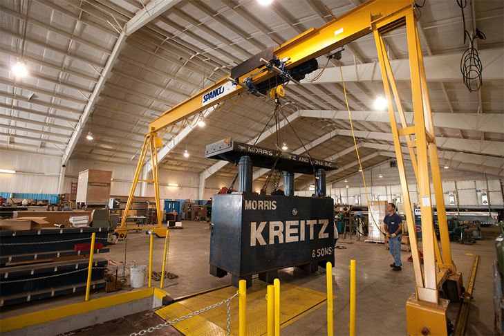
Spanco T-Series Gantry Cranes offer three-way adjustability for span, height, and tread.
Their adjustment flexibility allows use on multi-level floors, as well as passage through doorways, aisles, and under mezzanines or other overhead obstacles.
Three-Way Adjustability and Flexibility
Material handling solutions, such as our T-Series Gantry Cranes, are critical for helping facilities reduce employee injury and improve production processes. In addition to multiple adjustable features, the T-Series Gantry Crane meets Occupational Safety and Health Administration (OSHA) and American National Standards Institute (ANSI) requirements.

Options & Components
Photo Gallery


Additional Information
Features of Spanco T-Series Gantry Cranes
- Superior Stability: Engineered design leaves I-beam free to pivot as it self-centers over the load. The “true A-frame” design helps to maintain greater stability, virtually eliminating the swaying motion common to other 3-way adjustable gantry designs. Main legs, brace legs, and caster frames are made of heavy-gauge, square tubing with zinc-plated hardware.
- Adjustable Span: Exclusive Spanloc™ design securely holds the I-beam during adjustments and when set.
- Cantilever Options: Deliver materials through end of gantry; cantilever up to 25 percent of the rated capacity (4-foot max.) using a counterweight.
- Adjustable Height: Adjust in 6-inch intervals using push/pull pins on main legs.
- Adjustable Tread: A cable assembly is bolted inside the caster frame tubes to prevent overspreading.
- Heavy-Duty Casters: Four position, swivel-lock casters with moldon polyurethane wheels protect floors from damage.
Common Uses
Spanco is proud to serve customers in various industries, such as Space Exploration Technologies or SpaceX. SpaceX designs rockets and spacecraft and manufactures over half of its vehicles in-house. Their facility contains several work areas, including fabrication, machining, construction, and assembly cells.
Workers at the facility needed a material handling solution to move heavy loads throughout their facility with increased accuracy and precision. That solution came in the form of a two-ton Spanco T-Series Gantry Crane. The T-Series Gantry Crane also provides greater adjustability to meet the rapidly changing size requirements within the SpaceX facility.
Investing in a T-Series Gantry Crane allows SpaceX to improve production time and processing. By implementing the T-Series Gantry Crane, SpaceX could combine flexibility and precision while maintaining lift and cost-efficiency.
Spanco, Inc. warrants its products to be free from defects in material and workmanship as follows:
- Manual Systems & Equipment: Ten Years
- Motorized Systems & Equipment: One Year
- Paint & Finishes for Non-Aluminum Components: Two Years
Ten-Year Warranty Coverage:
- Defects in equipment material and workmanship of manual systems and equipment
- Wearable parts (workstation bridge crane end trucks and hoist trolley wheels only)
Spanco, Inc. warrants its manual workstation bridge crane, jib crane, and gantry crane products to be free from defects in material and workmanship for a period of ten (10) years or 20,000 hours, commencing on the date of shipment to the first retail purchaser. This warranty extends to non-wearable parts only, with the exception of the wheels supplied on manually operated workstation end trucks and hoist trolleys.
One-Year Warranty Coverage:
- Defects in equipment material and workmanship of motorized systems and equipment
Spanco, Inc. warrants motorized equipment to be free from defects in material and workmanship for a period of one (1) year or 2,000 hours, commencing on the date of shipment to the first retail purchaser.
Two-Year Warranty Coverage:
- Paint coatings and finishes for non-aluminum components
Spanco, Inc. warrants its paint and finishes for a period of two (2) years. Warranty claims related to coatings must be accompanied by documentation of the product’s application and environmental conditions from time of delivery to time of claim.
WARRANTY TERMS & CONDITIONS
All warranty claims must be approved by Spanco before any work is performed. Spanco’s obligation under this warranty is limited to the replacement or repair of Spanco products at the factory or separate location approved by Spanco. Other than the above mentioned warranty, Spanco will not honor any other warranties—whether expressed, implied, or statutory—and disclaims any warranties of merchantability or fitness for a particular purpose. Spanco has the right to reject any warranty claim due to harsh and/or inappropriate environmental conditions.
Spanco Is Not Liable for:
- Indirect, incidental, or consequential damages including lost profits, operating costs, loss of production, or travel expenses
- Components or accessories not manufactured by Spanco
- Defective equipment or system failure caused by misuse, negligence, and improper installation or maintenance
- Equipment that has been used in excess of its rated capacity or beyond its service factors
- Equipment that has been altered without Spanco’s written authorization
- Damage incurred by freight carriers
- Any loss, injury, or damage to persons or property resulting from failure or defective operation of material or equipment
Reimbursement Disclaimer:
- Written notice of any claimed system defect must be given to Spanco within ninety (90) days of shipment.
- All requests for reimbursement must be accompanied by proper documentation.
- Reimbursement is provided in the form of a credit unless otherwise approved by Spanco management.
- Reimbursement for labor will be provided at a maximum rate of $75 per hour.
- All reimbursement is subject to approval by Spanco management.
General Design Standards:
Spanco cranes are designed in conformance with the following applicable standards:
- Workstation Bridge Cranes: AISC Steel Construction Manual, OSHA 1910.179, ANSI B30.17, AWS D1.1/D1.6, and MMA MH27.2
- Gantry Cranes: AISC Steel Construction Manual, OSHA 1910.179, ANSI B30.17, AWS D1.1/D1.2/D1.6, and CMAA 74
- Jib Cranes: AISC Steel Construction Manual, OSHA 1910.179, ANSI B30.17, AWS D1.1/D1.6, and CMAA 74
All Spanco cranes have a design factor of 15% of the allowable capacity for the weight of the hoist and 25% for impact.
Fabrication Standards:
All welding performed during the manufacturing of Spanco cranes meets the following American Welding Society’s (AWS) standards: D1.2 for aluminum and D1.1 for steel.
Spanco is officially certified as an AWS Certified Welding Fabricator (CWF). This certification means that not only are all welders AWS Certified, but all processes and procedures adhere to AWS CWF requirements. Examples of requirements include annual calibration of all welding machines and Level 2 visual inspections on all load-bearing components.
Material Standards:
All aluminum used in the manufacturing of Spanco cranes meet ASTM International specification ASTM B308 for 6061-T6 aluminum.
All steel used in the manufacturing of Spanco cranes meets the following applicable ASTM International specifications:
Structural Steel Shapes: ASTM A-36
Structural Steel Pipes: ASTM A-53 Grade B
Structural Square and Rectangular Steel Tubing: ASTM A-500 Grade B
Steel plate and round bar used in Spanco cranes have minimum yield strengths of 36 KSI
Surface Preparation & Painting Procedures:
Spanco adheres to the standards of the Society for Protective Coatings (SSPC) for all product surface preparation. Prior to painting, all Spanco crane components are deburred and descaled using power tools equipped with sanding discs and wire wheels. Components are then washed utilizing a high-pressure/high-temperature biodegradable degreaser solution. Parts are wiped clean and allowed to dry before the painting process. During painting, all components surfaces are coated with a quick drying, semi-gloss enamel, applied to a minimum dry-film thickness of 2 to 3 mils. A finishing coat is applied with a hot, airless, electrostatic spray paint system. Painted components are cured at air temperature.
Deflection Guidelines:
The following guidelines for deflection and stress are followed by Spanco engineers during the crane design process:
- Workstation Bridge Cranes: All models are designed to approximately L/450
- Jib Cranes: Freestanding (100, 101, and 102 Series), Mast Style (200 and 201 Series), Wall-Mounted Cantilever (300 Series), Articulating (400, 401, and 402 Series), and Foundationless models (600 and 605 Series) are designed to approximately L/150; Wall-Mounted Bracket (301 Series) models are designed to approximately L/600 at midspan
- Workstation Jib Cranes: Wall-Mounted (WC Series) models are designed to approximately L/225; Freestanding (FR Series) models are designed to approximately L/150
- Gantry Cranes: All steel series models are designed to approximately L/600; Aluminum models are designed to approximately L/450
Quality Standards:
Spanco is an ISO 9001:2015 Registered corporation. This means that Spanco cranes are manufactured to standards ensuring safety, reliability, and the highest quality. Spanco’s ISO designation also allows for continuous improvement based on customer feedback.
- Inspect entire system annually or more frequently as defined by OSHA 1910.179. Inspection must be performed by a qualified person. Failure to do so may cause serious injury or death.
- This equipment, used as a crane, is not in any way designed for lifting, supporting, or transporting humans. Failure to follow specified load limitations can result in serious bodily injury or death.
- Inspect gantry for missing or broken parts before operating.
- Ensure the rated capacity is clearly labeled on each side of the I-beam.
- Do not lift more than the rated capacity.
- Do not adjust the height, span, tread, or disassemble crane when gantry is under load.
- Do not cantilever a load while the gantry is in the outboard bracing configuration.
- Do not move the gantry in the cantilever configuration while loaded.
- Do not cantilever a load from both ends of the I-beam. Only one end can be cantilevered at a time.
- Do not load the cantilevered end of the gantry without using a counterweight for the opposite end. For correct counterweight, consult the cantilever-loading chart attached to the gantry legs.
- Do not load gantry on an incline.
- Do not push or pull gantry with a forklift or other vehicle.
- Do not allow the load to swing or roll against support members.
- Do not anchor legs to the floor.
- Do not lift gantry when fully assembled.
- Push the gantry, not the load.
- When moving gantry, keep load as close to the floor as possible and position the load in the center of the I-beam.
- Be certain the load is directly beneath beam before load is lifted. Do not pull sideways on crane.
- Ensure the load is not attached to the floor and remove any obstacles that impede lifting.
- Secure trolley and hoist in the center of I-beam when adjusting height.
- Adjustments and/or repairs should be made in an area where it will have the least interference with operation.
- Increase the tread of the gantry as height is increased to maintain stability. Caster frame spread should be a minimum of 40 percent of overall height.
- Caster frames contain a preassembled aircraft cable assembly inside the tubes to prevent accidental overspreading of the legs. Do not remove this cable or unbolt the bolts on each end of the caster frame to which the cable is attached.
- To prevent the trolley from running off the I-beam, do not use without end stops bolted in place.
- Never stand under gantry when adjusting height or disassembling crane.