Ceiling-Mounted Workstation Bridge Cranes
- Capacities: 250 to 4,000 lbs.
- Bridge Lengths, overall: up to 40’
- Runway Spans: up to 40’
- Height — Floor-to-Trolley Clevis: determined by ceiling structure
Ceiling-mounted bridge cranes are great for applications with limited floorspace, facilities with large mobile equipment, and facility layouts that might change in the future. Ceiling-mounted systems also allow you to readily expand runway lengths and the number of bridges, and add links to monorail crane systems.
In addition to our custom engineered systems, we make pre-engineered systems that include everything but the hoist and sway bracing. All Spanco systems meet or exceed ANSI/ASME B30.17 standards for underhung cranes and monorails.

Options & Components
Photo Gallery


Need a System Fast?
Learn about our Fast-Track Offering
Find Out More
Additional Information
TRYING TO BOOST PRODUCTIVITY WITHOUT SACRIFICING SPACE?
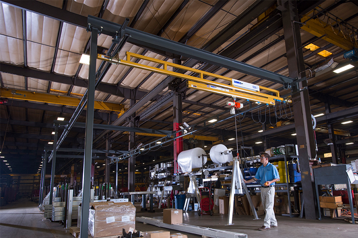
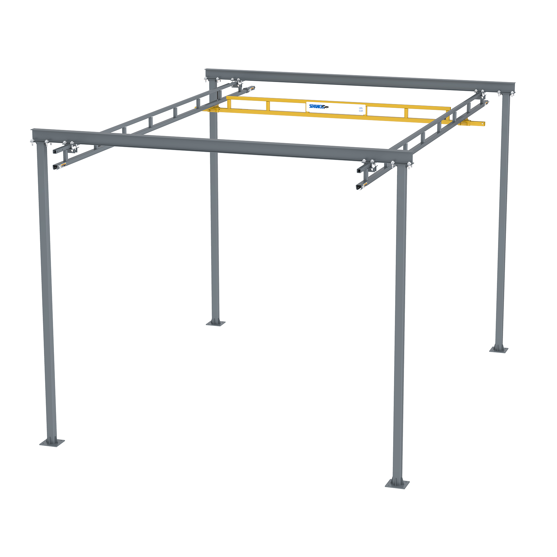
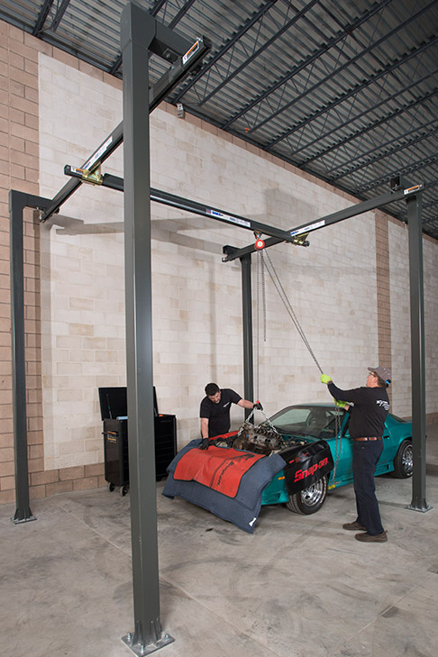
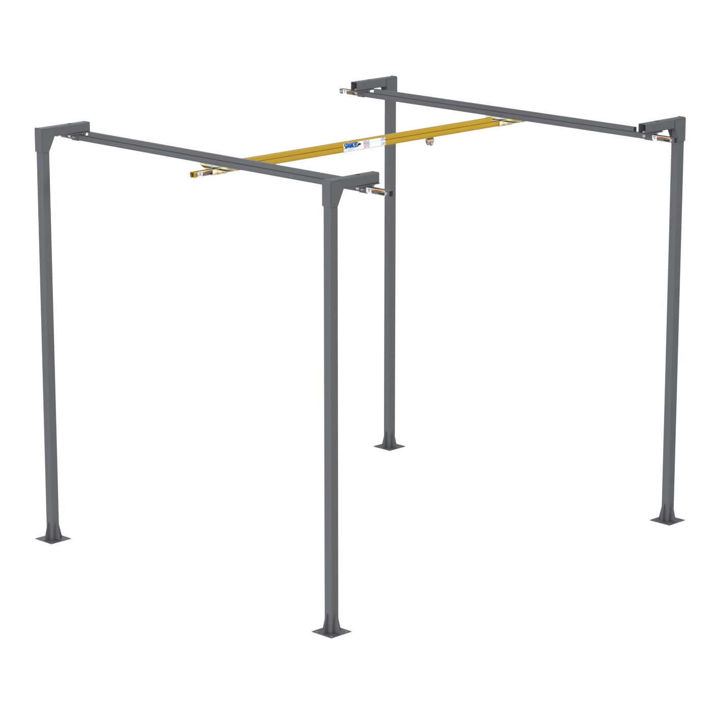
Spanco Ceiling-Mounted Workstation Bridge Cranes provide unlimited lifting coverage without sacrificing floor space or obstructing work areas. Our Ceiling-Mounted Workstation Bridge Cranes eliminate the need for steel supports, making them a cost effective and ergonomic material handling solution.
Spanco Ceiling-Mounted Workstation Bridge Cranes make the most of your existing building and production floor space. These systems:
- Hang from existing building beams or trusses
- Require no system support columns, no attachments to building columns, and no production floor space
- Allow you to readily expand runway lengths and the number of bridges, and add transitions to monorail crane systems
- Toronto Print Company Uses Spanco Ceiling-Mounted Systems To “Bridge” the Gaps in Their Facilities and Introduce A More Effective Print Process
- Workstation Bridge Crane is the Perfect Ergonomic Solution for New York Packaging Manufacturer
- Workstation Bridge Crane Provides Maintenance Shop With Lifting Versatility and Added Efficiency
- Workstation Bridge Cranes Streamline Blackmer’s Manufacturing Process
- Workstation Jib and Bridge Crane Improve Safety and Eliminate Worker Injury for Food Manufacturer
- Leading Energy Company Invests in a Customized Mixed-Capacity Bridge Crane to Leverage Productivity
- RV Manufacturer Finds Unique Application for Jib and Bridge Cranes
- Spanco Ceiling-Mounted Workstation Bridge Cranes with Telescoping Bridges Improve Efficiency for Agricultural Equipment Manufacturer
- Spanco Cranes Offer Increased Safety for Building Envelope Systems Manufacturer
- Dual Telescoping Bridge Crane Provides Extensive Coverage for Distribution Facility
Spanco, Inc. warrants its products to be free from defects in material and workmanship as follows:
- Manual Systems & Equipment: Ten Years
- Motorized Systems & Equipment: One Year
- Paint & Finishes for Non-Aluminum Components: Two Years
Ten-Year Warranty Coverage:
- Defects in equipment material and workmanship of manual systems and equipment
- Wearable parts (workstation bridge crane end trucks and hoist trolley wheels only)
Spanco, Inc. warrants its manual workstation bridge crane, jib crane, and gantry crane products to be free from defects in material and workmanship for a period of ten (10) years or 20,000 hours, commencing on the date of shipment to the first retail purchaser. This warranty extends to non-wearable parts only, with the exception of the wheels supplied on manually operated workstation end trucks and hoist trolleys.
One-Year Warranty Coverage:
- Defects in equipment material and workmanship of motorized systems and equipment
Spanco, Inc. warrants motorized equipment to be free from defects in material and workmanship for a period of one (1) year or 2,000 hours, commencing on the date of shipment to the first retail purchaser.
Two-Year Warranty Coverage:
- Paint coatings and finishes for non-aluminum components
Spanco, Inc. warrants its paint and finishes for a period of two (2) years. Warranty claims related to coatings must be accompanied by documentation of the product’s application and environmental conditions from time of delivery to time of claim.
WARRANTY TERMS & CONDITIONS
All warranty claims must be approved by Spanco before any work is performed. Spanco’s obligation under this warranty is limited to the replacement or repair of Spanco products at the factory or separate location approved by Spanco. Other than the above mentioned warranty, Spanco will not honor any other warranties—whether expressed, implied, or statutory—and disclaims any warranties of merchantability or fitness for a particular purpose. Spanco has the right to reject any warranty claim due to harsh and/or inappropriate environmental conditions.
Spanco Is Not Liable for:
- Indirect, incidental, or consequential damages including lost profits, operating costs, loss of production, or travel expenses
- Components or accessories not manufactured by Spanco
- Defective equipment or system failure caused by misuse, negligence, and improper installation or maintenance
- Equipment that has been used in excess of its rated capacity or beyond its service factors
- Equipment that has been altered without Spanco’s written authorization
- Damage incurred by freight carriers
- Any loss, injury, or damage to persons or property resulting from failure or defective operation of material or equipment
Reimbursement Disclaimer:
- Written notice of any claimed system defect must be given to Spanco within ninety (90) days of shipment.
- All requests for reimbursement must be accompanied by proper documentation.
- Reimbursement is provided in the form of a credit unless otherwise approved by Spanco management.
- Reimbursement for labor will be provided at a maximum rate of $75 per hour.
- All reimbursement is subject to approval by Spanco management.
General Design Standards:
Spanco cranes are designed in conformance with the following applicable standards:
- Workstation Bridge Cranes: AISC Steel Construction Manual, OSHA 1910.179, ANSI B30.17, AWS D1.1/D1.6, and MMA MH27.2
- Gantry Cranes: AISC Steel Construction Manual, OSHA 1910.179, ANSI B30.17, AWS D1.1/D1.2/D1.6, and CMAA 74
- Jib Cranes: AISC Steel Construction Manual, OSHA 1910.179, ANSI B30.17, AWS D1.1/D1.6, and CMAA 74
All Spanco cranes have a design factor of 15% of the allowable capacity for the weight of the hoist and 25% for impact.
Fabrication Standards:
All welding performed during the manufacturing of Spanco cranes meets the following American Welding Society’s (AWS) standards: D1.2 for aluminum and D1.1 for steel.
Spanco is officially certified as an AWS Certified Welding Fabricator (CWF). This certification means that not only are all welders AWS Certified, but all processes and procedures adhere to AWS CWF requirements. Examples of requirements include annual calibration of all welding machines and Level 2 visual inspections on all load-bearing components.
Material Standards:
All aluminum used in the manufacturing of Spanco cranes meet ASTM International specification ASTM B308 for 6061-T6 aluminum.
All steel used in the manufacturing of Spanco cranes meets the following applicable ASTM International specifications:
Structural Steel Shapes: ASTM A-36
Structural Steel Pipes: ASTM A-53 Grade B
Structural Square and Rectangular Steel Tubing: ASTM A-500 Grade B
Steel plate and round bar used in Spanco cranes have minimum yield strengths of 36 KSI
Surface Preparation & Painting Procedures:
Spanco adheres to the standards of the Society for Protective Coatings (SSPC) for all product surface preparation. Prior to painting, all Spanco crane components are deburred and descaled using power tools equipped with sanding discs and wire wheels. Components are then washed utilizing a high-pressure/high-temperature biodegradable degreaser solution. Parts are wiped clean and allowed to dry before the painting process. During painting, all components surfaces are coated with a quick drying, semi-gloss enamel, applied to a minimum dry-film thickness of 2 to 3 mils. A finishing coat is applied with a hot, airless, electrostatic spray paint system. Painted components are cured at air temperature.
Deflection Guidelines:
The following guidelines for deflection and stress are followed by Spanco engineers during the crane design process:
- Workstation Bridge Cranes: All models are designed to approximately L/450
- Jib Cranes: Freestanding (100, 101, and 102 Series), Mast Style (200 and 201 Series), Wall-Mounted Cantilever (300 Series), Articulating (400, 401, and 402 Series), and Foundationless models (600 and 605 Series) are designed to approximately L/150; Wall-Mounted Bracket (301 Series) models are designed to approximately L/600 at midspan
- Workstation Jib Cranes: Wall-Mounted (WC Series) models are designed to approximately L/225; Freestanding (FR Series) models are designed to approximately L/150
- Gantry Cranes: All steel series models are designed to approximately L/600; Aluminum models are designed to approximately L/450
Quality Standards:
Spanco is an ISO 9001:2015 Registered corporation. This means that Spanco cranes are manufactured to standards ensuring safety, reliability, and the highest quality. Spanco’s ISO designation also allows for continuous improvement based on customer feedback.
- Inspect entire system annually or more frequently as defined by OSHA 1910.179. Inspection must be performed by a qualified person. Failure to do so may cause serious injury or death.
- This equipment, used as a crane, is not in any way designed for lifting, supporting, or transporting humans. Failure to follow specified load limitations can result in serious bodily injury or death.
- Applications involving vacuums, magnets, or other high impact lifters are considered severe usage (continuous service) and require special design considerations. Please see the High-Impact Lifting Systems Protocol and contact factory for special design pricing.
- To prevent trolley/end truck running out of the track, do not operate crane without end stop bolts firmly secured in place on each end of the bridge crane track and on each end of each runway track.
- Runway end stops must be aligned longitudinally so bridge hits end stops simultaneously.
- Do not locate splice joints more than 12” from the runway support centers when aligning plain track runways.
- Do not cantilever the runway track ends more than 12” beyond the runway support centers (not including festoon storage area) on plain track runways.
- Do not locate truss splice joints more than 48” from the runway support centers when aligning trussed track runways.
- Do not cantilever the trussed runway ends more than 48” beyond the runway support centers (not including festoon storage area).
- Do not impact end stops at speed. Only impact end stops with caution.
- Never use end stops for repetitive bridge impacts.
- Do not skew bridge in runways.
Do not operate hoist or crane if cotter pins are not in place and properly bent over on both sides of hoist trolley. Check regularly that the cotter pins are in place and securing the hoist on the hoist trolley.
Applications involving vacuums, magnets, or other high-impact lifters are considered severe usage (continuous service) per the Monorail Manufacturers Association (MMA) and may require special design considerations. See below.
- Electromagnet lifting systems require the system capacity to be derated by 50%.
- Vacuum lifting systems that use an electric hoist never require the capacity to be derated.
- Vacuum lifting systems that use vacuum hose trolleys require the system to be derated by 50% if the system has any of the following attributes. Please contact Spanco with any questions about the system attributes below.
- The operational time (system is in motion) is consistently greater than 50% of the work period and the lifted load is consistently greater than 50% of the rated capacity.
- The equipment performs more than 20 lifts per hour.
- The average lift is 15 feet or more.
NOTE: Applications that exceed 40 lifts per hour can be problematic due to unusually high-cycle rates. If an application exceeds 40 lifts per hour, please provide as much information as possible about the lifting process and the item(s) being lifted.
Vacuum lifting systems that use vacuum hose trolleys and do not have any of the system attributes listed above do not require the system capacity to be derated.
- Workstation Bridge Crane Before Each Use Inspection Checklist
- Literature Request Form
- Workstation Crane Periodic Inspection Checklist
- Product Line Card
- Spanco Product Warranty
- Workstation Bridge Cranes Brochure
- Telescoping Workstation Bridge Crane Case Study Flyer
- Ceiling-Mounted Workstation Bridge Crane Bid Spec
- Ceiling-Mounted Alu-Track Workstation Bridge Cranes User Manual